Basic Info.
| Model NO. | Q665F-10S DN40 | Structure | Fixed Ball Valve |
|---|---|---|---|
| Type | Fixed Ball Valve | Function | Blow-Down Valve, Relief Valve |
| Temperature | Normal Temperature | Standard | GB ANSI JIS DIN |
| Application | Industrial Usage, Water Industrial Usage | Sales Volume | 5000sets |
| Inventory | 8000sets | Supply Capacity | 10000sets |
| Coating | Epoxy Coated | Transport Package | Wooden Case |
| Specification | 0.2ml³ | Trademark | BDV |
| Origin | Wenzhou China | HS Code | 8481804090 |
| Production Capacity | 5000 |
Product Description
https://bodavalve.en.made-in-china.com
Product Description
UPVC pneumatic ball valve, with light weight and strong corrosion resistance, is applied in multiple fields, such as pipeline systems for general pure water and raw drinking water, drainage and sewage pipeline systems, brine and seawater pipeline systems, acid alkali and chemical solution systems, and other industries.
Its quality has been recognized by a large number of users. Compact and beautiful appearance, light weight, easy to install, strong corrosion resistance, wide application range, hygienic and non-toxic material, wear-resistant, easy to disassemble, and easy to maintain.
| name | description |
| material quality | carbon steel , stainless steel |
| pressure | 0.6mpa~4mpa |
| caliber | DN40~DN450 |
| temperature | 0°C ~125°C |
| medium | water ,Steam ,oil |
| Connection method | wafer,flange, |
| Driving method | manual,electric,pneumatic,worm gear |
Detailed Photos
 UPVC pneumatic ball valve, with light weight and strong corrosion resistance, is applied in multiple fields, such as pipeline systems for general pure water and raw drinking water, drainage and sewage pipeline systems, brine and seawater pipeline systems, acid alkali and chemical solution systems, and other industries.
Its quality has been recognized by a large number of users. Compact and beautiful appearance, light weight, easy to install, strong corrosion resistance, wide application range, hygienic and non-toxic material, wear-resistant, easy to disassemble, and easy to maintain.


Choose the right 3-way multi-port ball valve for mixing or diverting flow
Published: September 6, 2018
Last updated: December 30, 2021
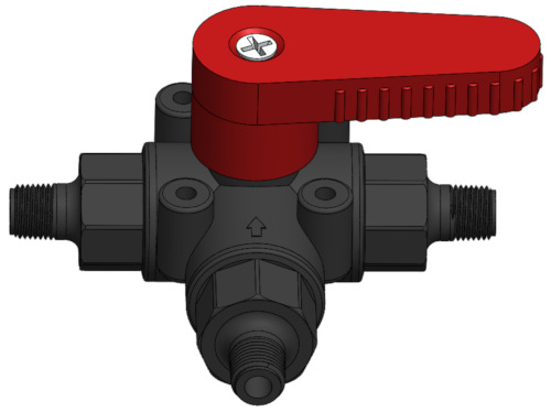
Flow through three-way ball valves
Two-way and three-way ball valves are the most common types of ball valves. Three-way ball valves are especially useful because they can be set up in ways that simplify the control of gas and fluid flow. For example, they can be used to divert the flow of oil from one tank to another.
Our online and PDF flow control valve catalogs provide access to a wide variety of miniature valve types, connection types, materials and sizes.
Three-way ball valves can
- Cut of or shut off flow
- Switch flow between two different sources
- Combine the flow from two different sources
- Alternate flow between two different destinations
- Divert flow coming from one source to another destination
- Split flow coming from one source between two outgoing destinations
This post focuses on the basic design differences between L-pattern (L-port) flow and T-pattern (T-port) flow in three-way ball valves. I will also describe some of the ways handle position in combination with the range of handle rotation are used to control flow through typical three-way ball valve designs.
In addition to the PDF e-book of this article, ISM also has a new, related reference resource available. It is our Three-Way Ball Valve Flow Patterns Chart.
The front view of a typical three-way ball valve with a handle that rotates parallel to the valve ports plane. These are also called horizontal type, horizontal version, horizontal ported and lateral version valves.

The front view of another common style of three-way ball valve. It has a handle that rotates at a right angle to the valve ports plane. These are also called vertical version, vertical type, vertical ported, upright and upright tee valves.

How is a three-way ball valve different from a two-way ball valve?
Two-way ball valves are widely used as shut-off valves for gases or liquids (media) moving through closed tube or pipe systems. This is because of their simplicity and reliability. Two-way valves have two ports or openings where pipe or tubing is connected to the valve. The ball in two-way ball valves has a single straight hole through it where the liquid or gas (media) passes through the valve.
Uncertain if a three-way ball valve is the right choice for your application? Get some tips and insights into choosing miniature ball valves.
The flow through a standard port ball valve is somewhat restricted because the bore through the ball inside the valve is smaller than the diameter of the pipes connected to the valve ports. An option for reducing or eliminating flow resistance through a ball valve is to use a full port ball valve.
Learn more about Full Port Ball Valves vs Standard Port ball valves. This blog post describes the differences between full port or full-bore ball valves and standard port valves. It also includes a list of FAQs describing some of the basics of ball valve design.
 Three-way ball valves have three ports or connections for pipe. In general, three-way valves can solve more complex flow control needs than two-way valves. This makes them useful for many types of process applications.
For example, one type of three-way ball valve can be used to mix purified water from one source with juice concentrate from another source. A slightly different three-way valve design could divert fuel flowing from one tank to another tank while still being able to shut off the flow of fuel entirely if needed.
When choosing the right three-way ball valve, it is important to both understand the key three-way valve design options and plan how the valves will be used. First, some basics.
What is a three-way ball valve?
Three-, four- and five-way ball valves are called multi-port valves. The three-way ball valve is the most common multi-port ball valve. A three-way ball valve has three ports or openings that are connected to piping or tubing for gas or fluid flow (media) to pass through. These ports are usually described as one inlet and two outlet ports or one outlet and two inlet ports depending upon the flow direction through the valve.
Three-way ball valves are popular because they are an economical and simple way of providing both shut off and flow direction control in a single valve body.
Ball Valve – Learn about Floating and Trunnion Mounted Ball Valves at HardHat Engineer
Although this technical blog is aimed at large-bore and high-pressure flow control, it contains some useful and very well illustrated information about three-way ball valve design.
Controlling flow through a three-way valve is done with a combination of how the piping is set up, the handle rotation of the valve ball and the flow path through the valve ball (the ball bore or porting).
Using the right valve type and setup, flow can be controlled in ways that meet one or more different process requirements such as
- Shut off flow completely
- Mix flow from two different sources
- Divert flow from one destination to another
- Split flow from one source between two different destinations
- Alternately block flow in one direction while allowing flow to continue in another
There is one simple but key internal design difference that determines what a three-way ball valve can do. This important design difference is the pattern of flow or port shape through the ball inside the valve. Most three-way ball valves have valve balls with flow patterns shaped like either a capital L (L-pattern flow, L-flow, L-port, two direction) or a capital T (T-pattern flow, T-flow, T-port, three direction).
I will describe the basics of three-way ball valves with both L-pattern and T-pattern flows, but I will describe L-pattern flow ball valves first. Having a clear understanding of L-pattern flow makes understanding T-pattern flow much easier.
L-pattern valve balls have flow paths shaped like a capital L
A typical L-pattern valve ball


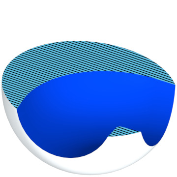
Notice that the stem slot for turning this valve ball is on top. This means the ball is made for a horizontal type three-way valve. If it was intended for a vertical type valve, the stem slot would be opposite one of the bore holes (ball flow path ports).
L flow patterns, sometimes called 90-degree balls, are most often used to allow flow from one common inlet port out into one of two different outlet ports. This is why L-pattern flow three-way ball valves are often called diverter valves.
What is a diverter valve?
Diverter, selecting or directional valves are alternate names used for L-pattern flow ball valves. This is because this valve design is widely used to divert or change the flow going out through one of two different valve outlets or ports. Manual three-way L-pattern ball valves used as diverter valves are usually installed with the bottom port of the valve body as the common or flow entry port.
The two flow paths available in this L-pattern flow three-way ball valve are to the left or to the right
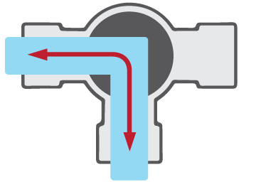
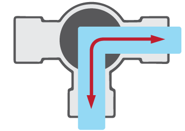
L-pattern flow ball valves with handles that can turn 90 degrees (a quarter turn of the handle) are also called two position valves. They can divert flow either to the left or to the right with one 90-degree turn of the handle.
PMBV Series – Diverter Ball Valves (spec sheet) from ISM
The PMBV series plastic three-way ball valves are typical L-port ball valves designed to be used as diverter valves without a cutoff position.
When their handles are allowed an additional 90-degree turn, 180 degrees total (a half turn of the handle) they can stop flow altogether. These are usually called three position valves.


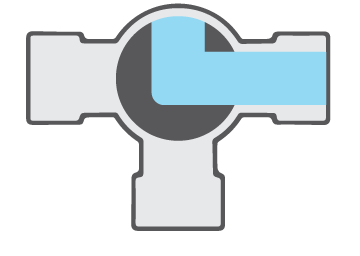
If the sweep of the handle rotation is not limited by built in valve handle stops, an L-flow pattern ball valve can also be rotated either 270 degrees (a three-quarter turn of the handle) or 360 degrees (a full turn of the handle). This freedom of rotation provides two possible shut-off positions.
An L-pattern flow three-way horizontal version ball valve has two potential shut-off positions.
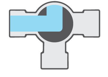

With a four-position valve, these two valve shutoff positions are only 90 degrees or a quarter turn apart.
Most horizontal type L pattern flow valves will have handles that are limited to 180 degrees of turn. This provides for three flow options:
- Left flow
- Right flow
- Cut off or shut off flow
Again, this type of L-pattern flow three-way ball valve is usually described as a three position valve.
The front view of a typical vertical type L-pattern flow three-way ball valve’s flow patterns
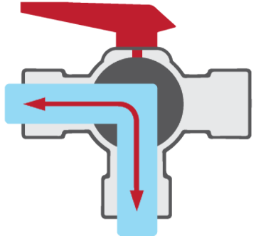
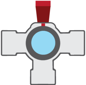
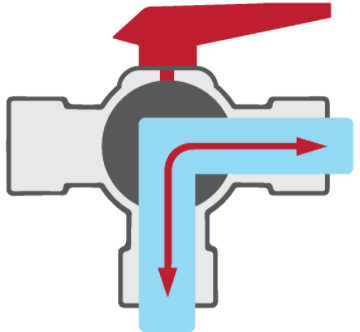
Vertical type L-pattern flow three-way ball valves have two possible flow paths and two possible off positions.
For a vertical type L-pattern flow ball valve, the bottom port or common port is always open. Turning the valve handle 180 degrees (a half turn) diverts flow either to the left or to the right (see the previous images). If the valve is rotated only 90 degrees (a quarter turn) in either direction though, the handle faces either the front or the back of the valve. In these handle positions, flow through the valve is cut off.
Many vertical type L-pattern flow valves will have handles that are limited to only turning 180 degrees, a half turn. This provides for all three options: left flow, right flow and one off position.
- BVPM Series – Female NPT Ball Valves (spec sheet) from ISM
The BVPM series of vertical type brass miniature valves include three-way ball valves. These three-way valves are typical L-port 180-degree rotation ball valves designed to be used as diverter valves plus one cutoff position. - BLV Series – Female NPT Ball Valves (spec sheet) from ISM
The BLV series of vertical type brass miniature valves include three-way ball valves. These three-way valves are typical L-port 180-degree rotation ball valves designed to be used as diverter valves plus one cutoff position. - PBV3 Series – 3-Way Ball Valves (spec sheet), PBV3 Series 3-Way Ball Valves – Panel Mount (spec sheet) and PBV3L Series – Large 3-Way Ball Valves (spec sheet) from ISM
These vertical type plastic miniature valves are typical L-port 180-degree rotation ball valves designed to be used as diverter valves plus one cutoff position.
Interested in finding out more about the pros and cons of plastic vs. metal ball valves?
Let’s look at horizontal type L-pattern flow in greater detail
In this L-pattern flow horizontal type three-way ball valve, the default handle position allows flow between the common valve port at the bottom and the left valve port.

If the valve handle is turned counterclockwise 90 degrees, the L-flow pattern ball inside the valve also rotates 90 degrees counterclockwise. It then diverts flow to the right instead. Flow now passes between the common or bottom port and the right port.

What are two position L-pattern flow ball valves?
This is where it starts getting a little tricky. A basic L-pattern flow three-way ball valve type (see above) is often limited to only this 90-degree turn of the handle. This very simple three-way ball valve is usually called a two-position valve. It is also called a diverter, selecting or directional valve.
Why do handles matter for three-way ball valves?
Limits on how far a ball valve handle can rotate are provided by handle stops of some sort (red arrows). These are usually extensions of the handle and the top of the valve body. They function by interfering with handle rotation. These stops prevent the handle from turning beyond a set range of motion.
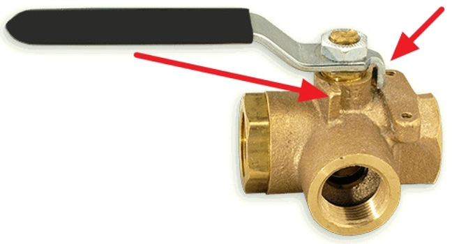
The handle stops built into this valve and its handle (red arrows) interfere with the movement of the valve handle limiting it to a 90-degree turn.
Three position L-pattern flow ball valves
Three position three-way L-flow pattern ball valves are also available. They have a 180-degree limit on the turn of the handle.
In a design like this, the handle position could start with a clear flow path between the bottom port and the left port (position 1). Turning the valve handle 90-degrees counterclockwise to its second position still allows flow through the valve, but this time the flow is between the bottom port and the right port.
Turning the valve an additional 90 degrees counterclockwise, 180 degrees total (position 3), cuts off all flow through the valve. These sort of L-pattern flow ball valves are usually called three-position valves: a starting position, a 90 degree turn and a 180 degree turn.


A 180-degree (three-position), L-pattern, three-way ball valve has two flow paths and one cutoff position.
Four position L-pattern flow ball valves

When the handle rotates the valve ball 90 degrees counterclockwise (position 2), the flow path changes and flow can now pass between the bottom common port and the right port.

Turning the handle an additional 90 degrees counterclockwise (position 3), 180 degrees from its original position, rotates the valve ball to a position where there is no flow possible between any of the valve ports and this valve is now ‘off’.

If the handle can be turned one more 90-degree turn counterclockwise (position 4), 270 degrees total, the valve ball still would not allow any flow and the valve would still be shut off.

Turning this valve’s handle another 90 degrees counterclockwise, 360 degrees total, returns it to its original starting position. Flow can again follow a path through the valve between the bottom common port and the left port.

In general, three-way ball valves are described by their features:
- Flow patterns (L-pattern or T-pattern flow)
- Handle orientation (horizontal type or vertical type)
- How many 90-degree turns or positions are allowed by the handle
These are typical handle position options provided in valve descriptions:
- Two positions (90 degrees)
- Three positions (180 degrees)
- Four positions (270 or 360 degrees)
For many L-pattern flow ball valves, additional flexibility is usually provided by making it possible to reposition the handle. These valves have handles that can be taken off the valve’s stem and then reattached in a different starting position.
Next, I would like to describe the basics of three-way ball valve T-pattern flow.
T-pattern ball flow paths are shaped like a capital T
A typical T-pattern valve ball
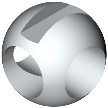
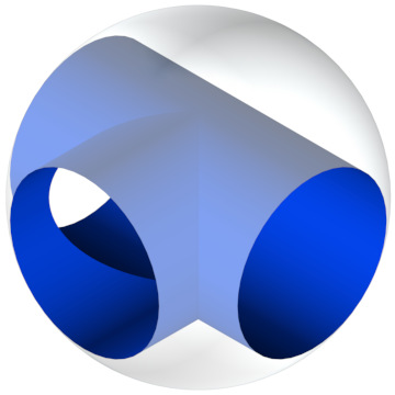

Notice that the stem slot for turning this valve ball is on top. This means the ball is made for a horizontal type three-way valve. If it was intended for a vertical type valve, the stem slot would be opposite the bottom or common bore hole.
T-pattern flow balls, sometimes called 180-degree balls, are widely used to take two inlet flows and combine them to flow out through one common outlet port. Depending on process requirements, the reverse is also possible. That is, split the flow coming in from one common port into two outgoing flows, each exiting the valve through a different valve port.
T-pattern flow valves are not just limited to splitting or dividing flow. They are also able to act like L-pattern flow valves and divert flow from one outlet port to the other.
Like L-pattern valves, T-pattern flow valves change flow paths with a quarter turn of their handle. Depending on the allowed range of handle motion, they can provide diversion flow, mixing or split flow and straight through flow.
In one important way, T-pattern flow ball valves are very different from L-flow pattern ball valves. Typical T-pattern flow valves cannot provide shut-off control. They can either limit flow to any two of the three valve ports or allow flow through all three valve ports at the same time. This is why T-flow pattern ball valves are sometimes called mixing valves.
What is a mixing valve?
Mixing valves are alternate names used for T-pattern flow ball valves. This is because this valve design is widely used to mix or combine flow coming two different sources. Ordinary manual three-way T-pattern ball valves used as mixing valves are usually installed with the bottom port of the valve body as the common outlet port.
Like the L-pattern flow ball valves, each 90-degree turn of the handle changes the flow path through the valve. And like the L-pattern flow valves, the turns of the handle may be limited by design using handle stops.
A T-pattern flow horizontal type three-way ball valve has four possible flow paths.
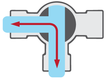
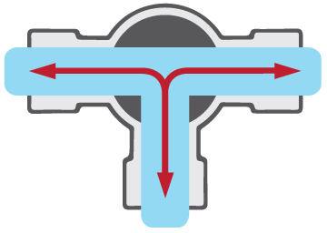
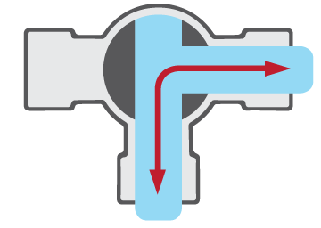
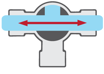
Notice that each flow pattern change, from left to right, each represents one 90-degree counterclockwise turn of the handle. Each turn of the handle causes a corresponding 90-degree turn of the valve ball. This changes the flow path through the valve.
T-pattern ball flow paths for vertical type three-way ball valves
Vertical type T-pattern flow ball valve are a little different than horizontal type valves. With vertical T-pattern valves, the bottom or common port is always open. Turning the valve handle 180 degrees does not change the flow path. If the valve is rotated only 90 degrees in either direction though, where the handle faces either the front or the back of the valve, flow is cut off.
Download a free ISM Three-way Ball Valves Flow Paths chart PDF for easy reference.
A typical vertical type T-pattern flow three-way ball valve’s flow patterns
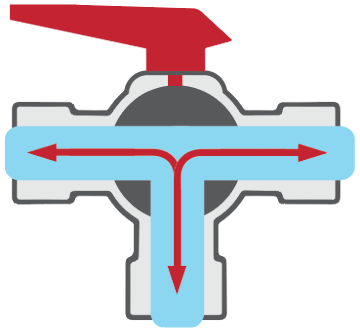

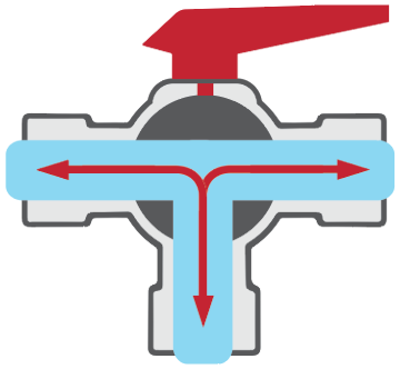
Vertical type T-pattern flow three-way ball valves have one possible flow path and one possible off position. The handle start position is on the left. From left to right, each image represents a 90-degree counterclockwise turn of the valve handle.
Most vertical type T-pattern flow valves will have handles that are limited to only turn either 90 degrees (one position) or 180 degrees (two positions). This provides both flow options:
- Flow cutoff
- Flow between all three ports
Vertical type T-pattern flow valves are sometimes called tee port valves or valves with tee port balls.
General applications for an L-port ball valve:
Diverter valves, shutoff valves, bypass valves, selecting valves, directional valves
- Divert flow going to one storage tank to a different tank
- Change the source of flow from one pump to a different pump
- Change the source of flow source from one tank to a different tank
- Divert flow from a chiller or heater to accommodate seasonal demand
- Cut off all flow while still being able to choose between two flow destinations or two flow sources
General applications for a T-port ball:
Sample valves, purging valves, mixing valves, bypass valves, constant flow valves
- Combine flow from two different sources
- Split flow between two different destinations
- Alternate flow between two different sources
- Allow the flow from two different sources to mix
- Alternate flow between two different destinations
Conclusion
Generally, three-way ball valves are described based on their flow patterns (L-pattern or T-pattern flow), handle orientation (horizontal type or vertical type) and the number of 90 degree turns the handle is allowed to rotate:
- Two positions (90 degrees)
- Three positions (180 degrees)
- Four positions (270 or 360 degrees)
Depending on how the valve ball is drilled and the piping configuration, gas and liquid flow can be diverted, mixed, blocked in one direction or shut off completely. Multiport valves save space and can eliminate an extra tee and valve. Understanding basic three-way ball valve design options makes it easier to choose the right three-way valve and easier to plan its installation.
Other related blog posts
- 7 Tips for Choosing a Miniature Ball Valve >>
Need a small ball valve but aren't sure what matters? Get tips & information that help you get a jump start narrowing down the options. Find out more about designs, specifications, materials & more.
- Five Tips for Selecting the Right Valve >>
Learn some tips for selecting the correct type of valve for your application. Choosing the right valve begins with knowing the role it plays. Knowing its purpose plus a few more key considerations will simplify and speed up any valve selection process.
- Full Port Ball Valves vs Standard Port >>
The differences between full port or full bore ball valves and standard port valves. Includes FAQs describing some of the basics of ball valve design.
- Miniature Ball Valves: Plastic, Brass or Stainless Steel? >>
An overview of what matters when choosing a ball valve body material. Temperature, pressure and corrosion resistance are key issues when the choice is between plastic and metal. When metal is definitely the way to go, the most common mini ball valve body metals are brass and stainless steel. Each has its pros and cons.
- Extruded, Forged or Cold-Drawn Brasses for Miniature Valves >>
An overview of how brass is formed, worked and shaped to make miniature ball and check valves. Brass is a great material choice for miniature valves. Learn more about why brass is such a useful metal for making valves. This post also covers some of the basics of the most important industrial brass forming techniques.
- Stainless Steel Materials for Miniature Flow Control Valves >>
Stainless steel materials are strong, pressure and temperature resistant, tough, less reactive and more durable than cast iron, ductile iron, brass or copper. They are a great metal choice for fluid and gas flow control valves.
How ISM can help you find the right miniature valve for your application
Personalized customer service and resources available at the ISM website can be a great help when selecting a valve. Available online resources include chemical compatibility reference guides, dimensional drawings and product data sheets. Our online and PDF flow control valve catalogs provide access to a wide variety of miniature valve types, connection types, materials and sizes.


